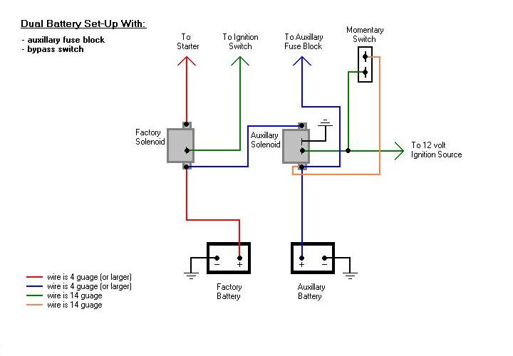
When it comes to understanding the intricate workings of electrical systems in vehicles or machinery, having a clear understanding of the 12v Continuous Duty Solenoid Wiring Diagram is crucial. This diagram serves as a roadmap for connecting various electrical components and ensuring the smooth operation of the system.
Importance of 12v Continuous Duty Solenoid Wiring Diagram
1. Provides a visual representation of the electrical connections
2. Helps in identifying the correct wiring configuration
3. Ensures proper installation of the solenoid
4. Facilitates troubleshooting of electrical issues
Reading and Interpreting 12v Continuous Duty Solenoid Wiring Diagram
1. Identify the components: Understand the symbols used to represent different components such as solenoid, battery, and switches.
2. Follow the flow of current: Trace the path of the current through the diagram to ensure all connections are correct.
3. Pay attention to colors and labels: Differentiate between wires by color and pay attention to any labels or markings on the diagram.
Using 12v Continuous Duty Solenoid Wiring Diagram for Troubleshooting
1. Locate the problem area: Use the diagram to pinpoint the area where the electrical issue may be occurring.
2. Check connections: Ensure all connections are secure and follow the correct wiring configuration as per the diagram.
3. Test components: Use a multimeter to test the continuity of wires and check the functionality of components.
Safety Tips for Working with Electrical Systems
- Always disconnect the power source before working on any electrical system.
- Use insulated tools to prevent electric shock.
- Wear appropriate protective gear such as gloves and goggles.
- Avoid working on electrical systems in wet or damp conditions.
- Seek professional help if unsure about any aspect of electrical wiring.
12v Continuous Duty Solenoid Wiring Diagram
12 Volt Continuous Duty Solenoid Wiring Diagram

12 Volt Continuous Duty Solenoid Wiring Diagram – Wiring Draw And Schematic

Cole Hersee Continuous Duty Solenoid Wiring Diagram – Herbally

Continuous Duty Solenoid Wiring Diagram – Artled

12 Volt Continuous Solenoid Wiring – Wiring Flow Schema
