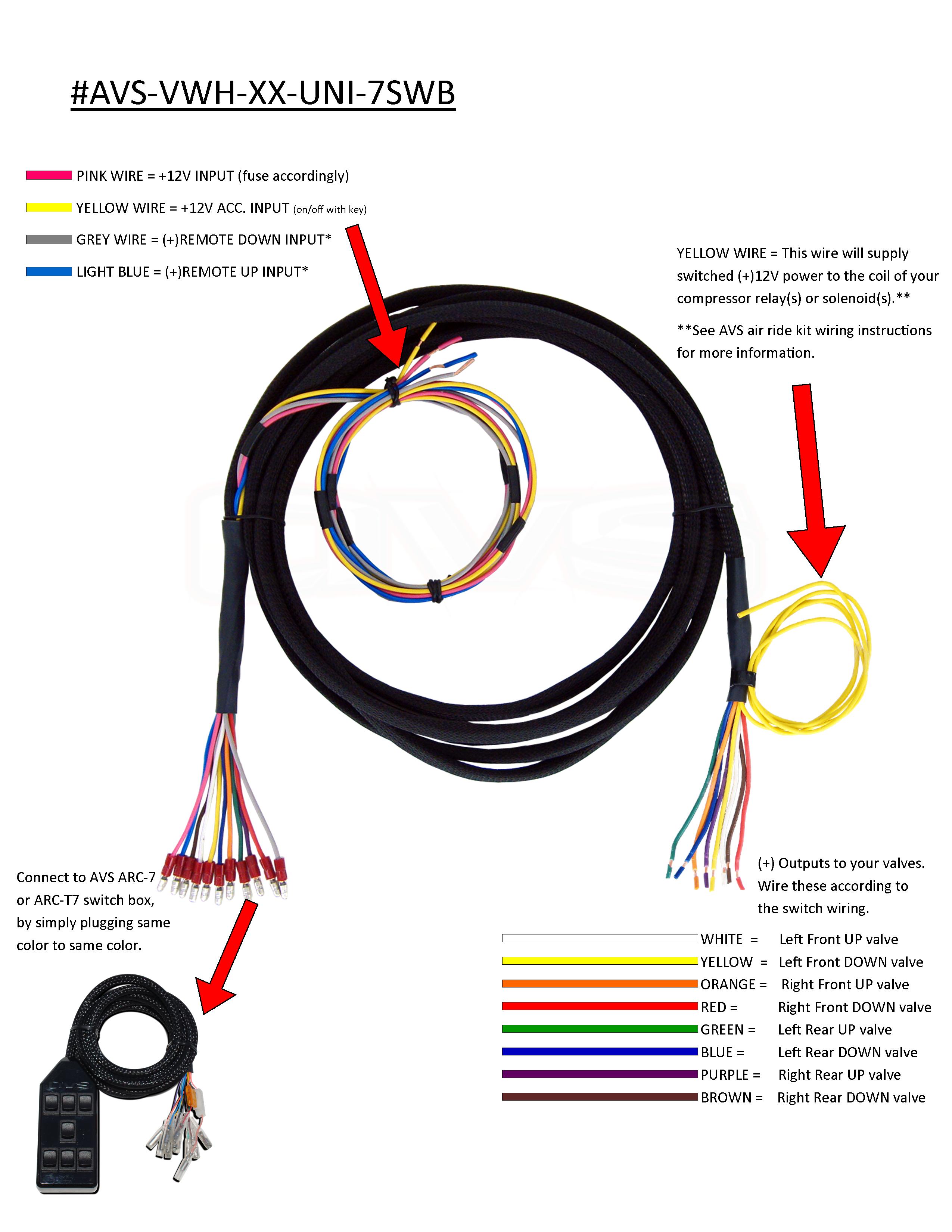
When it comes to customizing and optimizing the performance of your vehicle’s air ride system, having a solid understanding of the Air Ride Switch Box Wiring Diagram is essential. This diagram serves as a roadmap for connecting all the components of your air ride system, ensuring proper functionality and performance.
Importance of Air Ride Switch Box Wiring Diagram
- Ensures proper connection of all components
- Helps prevent electrical shorts and malfunctions
- Aids in troubleshooting electrical issues
- Allows for customization and modification of the air ride system
Reading and Interpreting Air Ride Switch Box Wiring Diagram
Reading and interpreting an Air Ride Switch Box Wiring Diagram may seem daunting at first, but with a bit of practice, it can become second nature. Here are some tips to help you effectively understand the diagram:
- Identify the components labeled in the diagram
- Follow the lines and connections to determine how the components are linked
- Refer to the legend or key for any symbols or abbreviations used
Using Air Ride Switch Box Wiring Diagram for Troubleshooting
When faced with electrical issues in your air ride system, the Wiring Diagram can be a valuable tool for troubleshooting. By following the diagram and checking for continuity, voltage, and proper connections, you can pinpoint the source of the problem and make necessary repairs.
Safety Tips for Working with Air Ride Switch Box Wiring Diagram
- Always disconnect the power source before working on the wiring
- Use insulated tools to prevent electrical shocks
- Double-check all connections before powering up the system
- Consult a professional if you are unsure about any aspect of the wiring diagram
Air Ride Switch Box Wiring Diagram
Air Ride Switch Box Wiring Diagram

1971-1996 Chevy Impala Elite EZ Air Ride Suspension Kit – B Body – PLUS

Dual Compressor Wiring Kit by AVS – Complete Air Ride

Single Compressor Wiring Kit by AVS – Complete Air Ride

Harley Fast Up Air Ride Rear Kit & Diagram | Speed By Design

Understanding Air Ride Pressure Switch Wiring Diagrams For Vehicles
