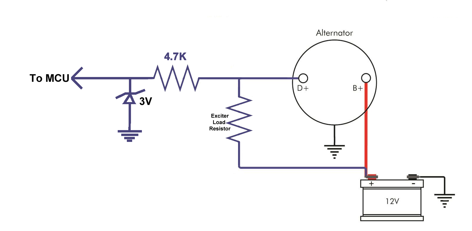
An alternator exciter wiring diagram is a crucial tool for understanding and troubleshooting the electrical system in a vehicle or machinery. It provides a detailed visual representation of how the alternator exciter circuit is wired, helping mechanics and technicians to identify and fix any issues that may arise.
Why Alternator Exciter Wiring Diagrams are Essential
- Helps in understanding the electrical connections within the alternator exciter circuit
- Aids in diagnosing and fixing electrical problems efficiently
- Ensures proper installation and maintenance of the alternator exciter system
Reading and Interpreting Alternator Exciter Wiring Diagrams
When looking at an alternator exciter wiring diagram, it’s important to pay attention to the symbols, colors, and labels used. Here are some tips for effectively reading and interpreting these diagrams:
- Identify the components and their connections within the diagram
- Follow the wiring paths to understand how the circuit is laid out
- Refer to the key or legend to understand the symbols used in the diagram
Using Alternator Exciter Wiring Diagrams for Troubleshooting
Alternator exciter wiring diagrams are invaluable for troubleshooting electrical problems in a vehicle or machinery. By following the wiring diagram, technicians can:
- Identify faulty connections or components within the circuit
- Trace the source of electrical issues such as no output or low output from the alternator
- Ensure that all connections are secure and properly grounded
Importance of Safety
Working with electrical systems can be dangerous, so it’s crucial to prioritize safety when using alternator exciter wiring diagrams. Here are some safety tips and best practices to follow:
- Always disconnect the battery before working on any electrical components
- Use insulated tools to avoid electrical shocks
- Avoid working on electrical systems in wet or damp conditions
- Double-check all connections before re-energizing the system
Alternator Exciter Wiring Diagram
Microcontroller – How To Monitor An Alternator Exciter Wire With Mcu

Alternator Exciter Wiring Diagram

Alternator Exciter Wiring Diagram – Cadician's Blog

Cummins Alternator Wiring Diagram – Fab Port

What Is An Alternator Exciter Wire

Alternator Exciter Wiring Diagram – Cadician's Blog
