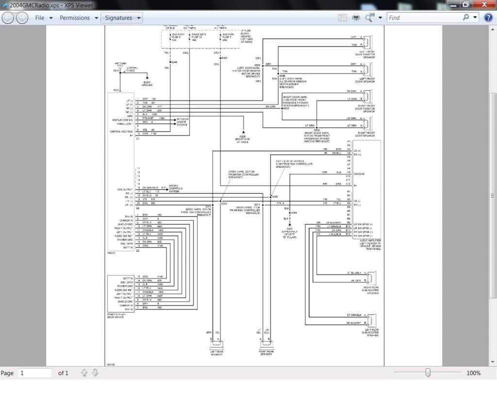
When working with Apollo 635/636 circuit board wiring diagrams, it is important to understand the layout and connections of the electrical components in order to troubleshoot and repair any issues that may arise.
Why Apollo 635/636 Circuit Board Wiring Diagrams are Essential
Apollo 635/636 circuit board wiring diagrams are essential for several reasons:
- They provide a visual representation of the electrical connections on the circuit board.
- They help identify the various components and their corresponding wiring.
- They guide technicians in understanding the circuitry and diagnosing problems effectively.
How to Read and Interpret Apollo 635/636 Circuit Board Wiring Diagrams
Reading and interpreting Apollo 635/636 circuit board wiring diagrams requires a systematic approach:
- Start by identifying the key components on the diagram, such as relays, switches, and connectors.
- Follow the wiring lines to trace the connections between components.
- Refer to the legend or key for any symbols or abbreviations used on the diagram.
Using Apollo 635/636 Circuit Board Wiring Diagrams for Troubleshooting
Apollo 635/636 circuit board wiring diagrams are valuable tools for troubleshooting electrical problems:
- Compare the actual wiring on the circuit board to the diagram to identify any discrepancies.
- Check for loose connections, damaged wires, or faulty components based on the diagram.
- Use the diagram to isolate the specific area of the circuit that may be causing the issue.
Importance of Safety
When working with electrical systems and using wiring diagrams, safety should always be the top priority. Here are some safety tips and best practices to keep in mind:
- Always turn off the power before working on any electrical equipment.
- Use insulated tools to prevent electrical shock.
- Avoid working on live circuits whenever possible.
- Double-check connections before powering up the system to prevent short circuits.
Apollo 635/636 Circuit Board Wiring Diagram
Apollo 635/636 Circuit Board Wiring Diagram – alternator

Apollo 635/636 Circuit Board Wiring Diagram Usb Breakout Board Wiring

apollo 635/636 circuit board wiring diagram

Apollo 635/636 Circuit Board Wiring Diagram – alternator

Apollo 635/636 Circuit Board Wiring Diagram Usb Breakout Board Wiring

Apollo 635/636 Circuit Board Wiring Diagram – diagramwirings
