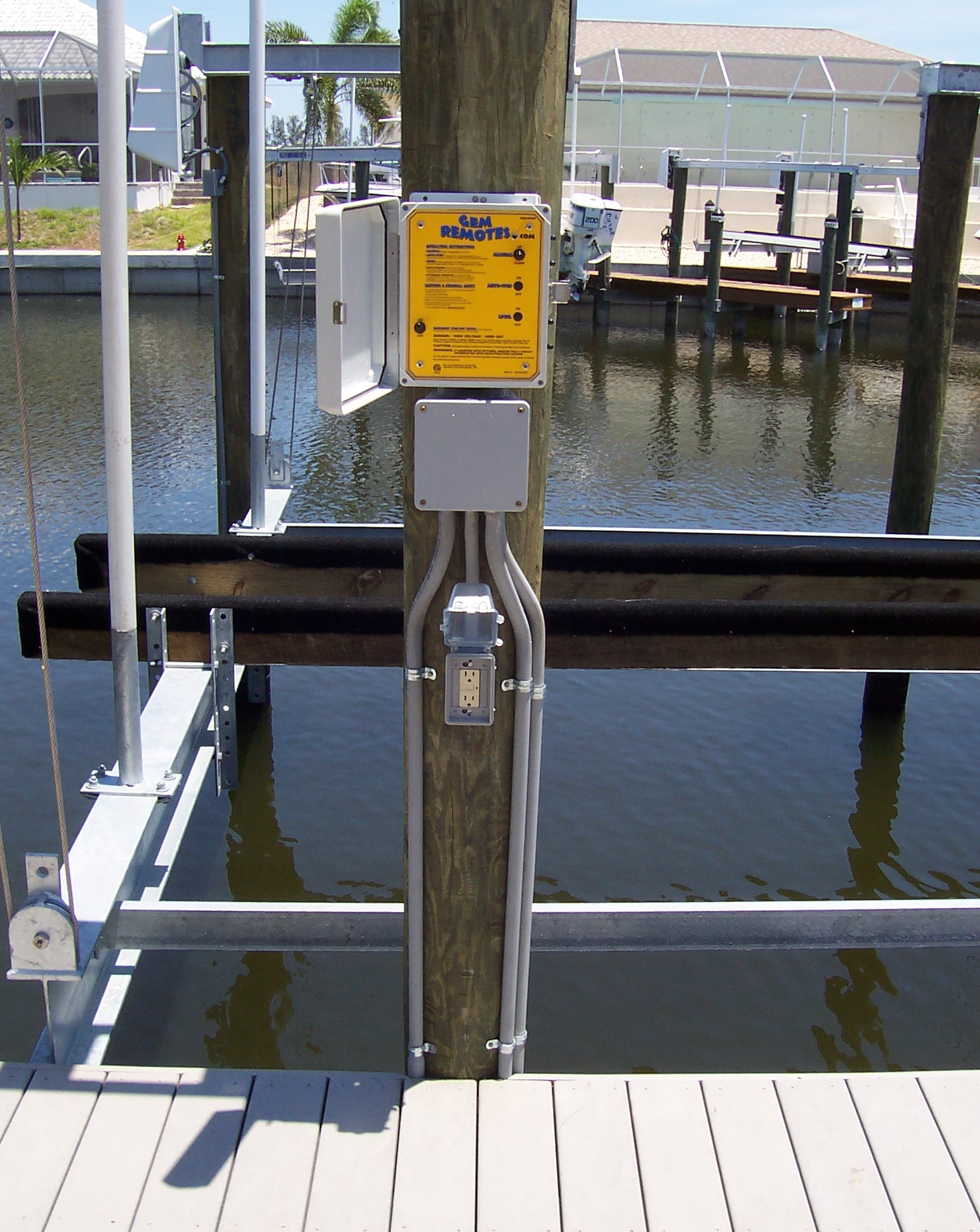
Boat Dock Wiring Diagrams are essential tools for anyone working with electrical systems on a boat dock. These diagrams provide a visual representation of the electrical connections and components, helping users to understand how the system is wired and how power flows throughout the dock.
Why Boat Dock Wiring Diagrams are Essential
- Ensure proper installation of electrical components
- Prevent electrical hazards and accidents
- Aid in troubleshooting electrical issues
- Comply with safety regulations and standards
How to Read and Interpret Boat Dock Wiring Diagrams
When reading a Boat Dock Wiring Diagram, it is important to understand the symbols and labels used to represent different components. The diagram will typically include symbols for power sources, switches, outlets, and other electrical devices. By following the lines and connections on the diagram, users can trace the flow of electricity and identify potential issues.
Using Boat Dock Wiring Diagrams for Troubleshooting
Boat Dock Wiring Diagrams can be invaluable when troubleshooting electrical problems on a boat dock. By referencing the diagram, users can identify the location of specific components, test for continuity, and isolate the source of the issue. This can save time and effort by providing a roadmap for diagnosing and fixing electrical problems.
Importance of Safety
Working with electrical systems can be dangerous, so it is important to prioritize safety at all times. When using Boat Dock Wiring Diagrams, follow these safety tips:
- Always turn off power before working on electrical systems
- Use proper insulation and protective gear
- Avoid working in wet or damp conditions
- Consult a professional if you are unsure about any aspect of the wiring diagram
Boat Dock Wiring Diagram
How To Wire A Boat | Beginners Guide With Diagrams | New Wire Marine

Dock Wiring Diagram Database

Boat dock wiring – Compass Electric

Fort Lauderdale Boat Dock Electrical Wiring Power And Lighting

Wiring A Boat From Scratch

Boat Dock Wiring Diagram Collection – Wiring Diagram Sample
