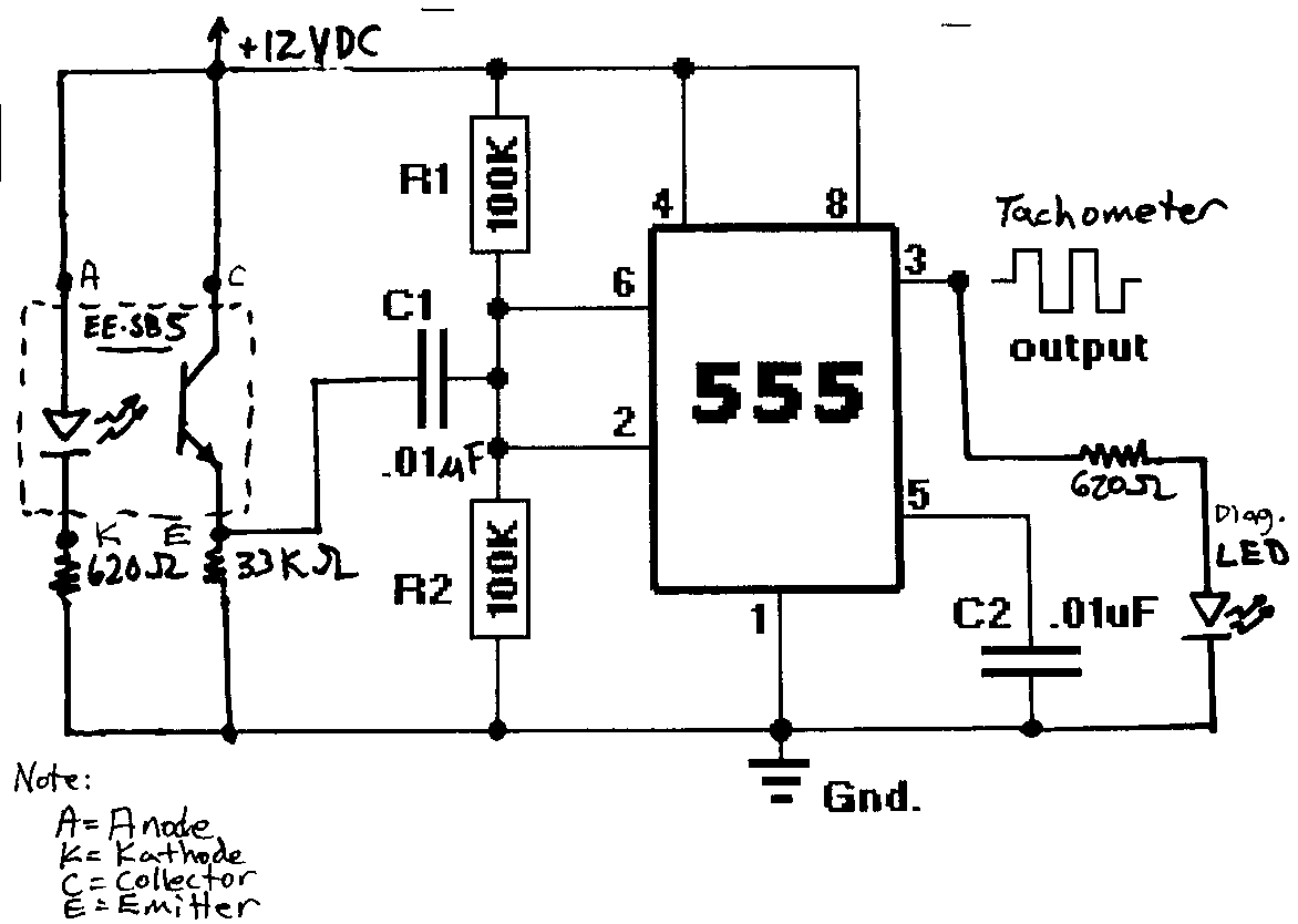
Understanding the Diesel Tach Wiring Diagram is crucial for anyone working with diesel engines. The wiring diagram provides a visual representation of the electrical system in a diesel engine, including the tachometer, which measures the engine’s speed in revolutions per minute (RPM).
Why Diesel Tach Wiring Diagrams are Essential
- Helps in understanding the electrical system of a diesel engine
- Essential for diagnosing and troubleshooting electrical issues
- Ensures proper installation of tachometers and other electrical components
Reading and Interpreting Diesel Tach Wiring Diagrams
When reading a Diesel Tach Wiring Diagram, it’s important to understand the symbols and color codes used. The diagram typically includes key components such as the tachometer, ignition switch, battery, and ground connections. By following the lines and connections, you can trace the electrical flow and identify any issues.
Using Diesel Tach Wiring Diagrams for Troubleshooting
- Identify loose or disconnected connections
- Check for blown fuses or damaged wires
- Verify proper grounding and voltage levels
Importance of Safety
Working with electrical systems can be dangerous, so it’s important to follow safety precautions when using wiring diagrams:
- Always disconnect the battery before working on the electrical system
- Use insulated tools to prevent electrical shocks
- Avoid working on electrical components in wet or damp conditions
- If unsure, consult a professional mechanic or electrician
Diesel Tach Wiring Diagram
Pro Comp Tach Wiring Diagram – Wiring Diagram Pictures

Vdo Diesel Tachometer Wiring – Complete Wiring Schemas

OEM Tach wiring diagram – Dodge Diesel – Diesel Truck Resource Forums

Diesel Tachometer Wiring Diagram – Esquilo.io

Diesel Tachometer. under Repository-circuits -33304- : Next.gr

Vdo Diesel Tachometer Wiring Diagram – Wiring Diagram Pictures
