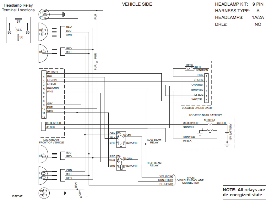
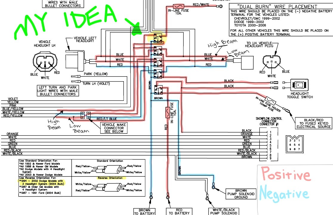
Fisher Plow Light Wiring Diagrams are essential tools for anyone working on Fisher plow systems, as they provide a detailed schematic of the wiring connections for the plow lights. These diagrams are crucial for ensuring that the lights are properly connected and functioning correctly.
Why Fisher Plow Light Wiring Diagrams are Essential
- Ensure proper wiring connections
- Prevent electrical issues or malfunctions
- Aid in troubleshooting problems
- Ensure safety and compliance with regulations
Reading and Interpreting Fisher Plow Light Wiring Diagrams
Reading and interpreting Fisher Plow Light Wiring Diagrams can seem daunting at first, but with a little practice, you can easily decipher the information they provide. Here are some tips to help you understand these diagrams:
- Identify the components shown in the diagram
- Follow the lines to trace the wiring connections
- Refer to the legend or key for symbols and color codes
- Pay attention to the direction of the electrical flow
Using Fisher Plow Light Wiring Diagrams for Troubleshooting
Fisher Plow Light Wiring Diagrams are invaluable when it comes to troubleshooting electrical problems with plow lights. By following the wiring diagram and checking for continuity, shorts, or breaks in the wiring, you can quickly pinpoint the issue and make the necessary repairs.
Importance of Safety
When working with electrical systems and using wiring diagrams, it is crucial to prioritize safety. Here are some safety tips and best practices to keep in mind:
- Always disconnect the power source before working on any electrical components
- Use insulated tools to prevent electrical shocks
- Avoid working on electrical systems in wet or damp conditions
- Double-check all connections and wiring before restoring power
Fisher Plow Light Wiring Diagram
Fisher Minute Mount 2 Headlight Wiring Diagram – Schema Wiring Diagram

Fisher Plow Light Wiring Diagram – Database – Wiring Collection

66610 MVP Western / Fisher Unimount Truck side 12 pin light wiring

fisher plow wiring diagram minute mount 2 – Wiring Diagram and
Fisher Plow Lights | Wiring Diagram Image

How dpo I wire a fisher snow plow wiring harness that has three prong
