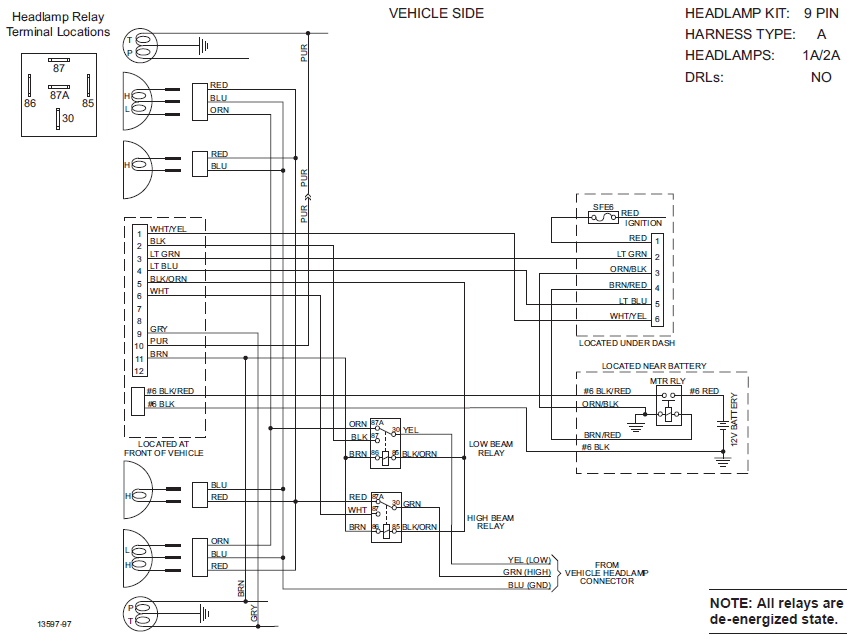
Fisher Plow Lights Wiring Diagram is a crucial tool for anyone working on the electrical system of a Fisher plow. This diagram provides a visual representation of the wiring layout and connections for the plow lights, making it easier to troubleshoot and repair any issues that may arise.
Why Fisher Plow Lights Wiring Diagram are Essential
Understanding the Fisher Plow Lights Wiring Diagram is essential for the following reasons:
- Helps identify the correct wiring connections for the plow lights
- Aids in troubleshooting electrical issues
- Ensures proper installation and functioning of the plow lights
How to Read and Interpret Fisher Plow Lights Wiring Diagram
When looking at a Fisher Plow Lights Wiring Diagram, it’s important to know how to interpret the information provided. Here are some tips:
- Identify the components and their connections on the diagram
- Follow the wiring paths to understand how electricity flows through the system
- Pay attention to color codes and symbols used in the diagram
Using Fisher Plow Lights Wiring Diagram for Troubleshooting
When faced with electrical problems in the plow lights, the wiring diagram can be a valuable tool for troubleshooting. Here’s how you can use it:
- Locate the specific circuit or component that is causing the issue on the diagram
- Check for any breaks or loose connections in the wiring
- Use a multimeter to test for continuity and voltage at various points in the circuit
Importance of Safety
Working with electrical systems can be dangerous, so it’s important to prioritize safety when using Fisher Plow Lights Wiring Diagram. Here are some safety tips to keep in mind:
- Always disconnect the power source before working on the electrical system
- Wear appropriate protective gear, such as gloves and safety glasses
- Avoid working on the system in wet or damp conditions
- Double-check all connections and wiring before applying power to the system
Fisher Plow Lights Wiring Diagram
The Ultimate Guide to Understanding Fisher Plow Lights Wiring Diagrams

The Ultimate Guide to Understanding Fisher Plow Lights Wiring Diagrams

Fisher Plow Headlight Wiring Diagram

Fisher Plow Light Wiring Diagram – Database – Wiring Collection

fisher plow lights troubleshooting – Wiring Digital and Schematic
