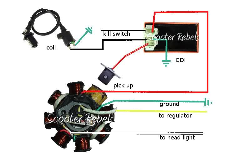
When it comes to understanding the electrical system of a Gy6 engine, the Gy6 Electric Choke Wiring Diagram is an essential tool. This diagram provides a detailed outline of the electrical connections and wiring configurations for the electric choke system in a Gy6 engine. By following this diagram, mechanics and enthusiasts can easily identify and troubleshoot any issues related to the electric choke system.
Importance of Gy6 Electric Choke Wiring Diagram
- Helps in understanding the electrical connections of the electric choke system
- Aids in troubleshooting electrical issues effectively
- Ensures proper installation and connection of the electric choke system
Reading and Interpreting Gy6 Electric Choke Wiring Diagram
When reading a Gy6 Electric Choke Wiring Diagram, it is important to understand the symbols and color codes used in the diagram. Each wire and connection is labeled with specific symbols and colors to indicate its function and location. By following the key or legend provided with the diagram, individuals can easily interpret the wiring configurations and make necessary adjustments or repairs.
Using Gy6 Electric Choke Wiring Diagram for Troubleshooting
- Identify any loose or disconnected wires in the electric choke system
- Check for continuity and proper voltage levels in the electrical connections
- Trace the wiring path to identify any damaged or faulty components
Safety Tips for Working with Gy6 Electric Choke Wiring Diagram
- Always disconnect the battery before working on any electrical system
- Use insulated tools to prevent electrical shocks
- Avoid working on electrical systems in wet or damp conditions
- Double-check all connections and wiring before powering up the system
Gy6 Electric Choke Wiring Diagram
Ruckus GY6 swap wiring diagram

wiring diagram gy6 – Green Lab

gy6 auto choke wiring diagram

gy6 wiring harness

Gy6 Electric Choke Wiring Diagram – Wiring Diagram

Gy6 Electric Choke Wiring Diagram – Wiring Diagram Pictures
