Opening Paragraph:
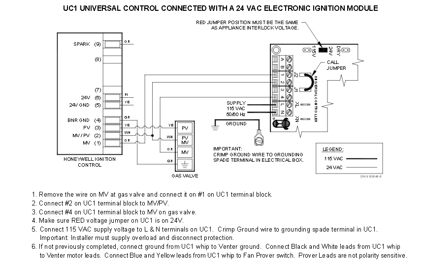
An inducer motor wiring diagram is a crucial tool for understanding the electrical connections in an HVAC system. By following this diagram, technicians can ensure that the inducer motor is wired correctly, preventing malfunctions and ensuring optimal performance.
Why Inducer Motor Wiring Diagrams are Essential:
Inducer motor wiring diagrams are essential for several reasons:
- They provide a visual representation of the electrical connections in the system.
- They help technicians identify the correct wires and terminals for connecting the inducer motor.
- They ensure that the motor is wired according to the manufacturer’s specifications, preventing damage and malfunctions.
How to Read and Interpret Inducer Motor Wiring Diagrams:
When reading an inducer motor wiring diagram, technicians should follow these steps:
- Identify the components and terminals shown in the diagram.
- Trace the electrical connections from the power source to the inducer motor.
- Refer to the legend or key to understand the symbols and color codes used in the diagram.
Using Inducer Motor Wiring Diagrams for Troubleshooting:
Inducer motor wiring diagrams can be used for troubleshooting electrical problems by:
- Identifying faulty connections or components that may be causing issues.
- Checking for continuity and proper voltage levels at each terminal.
- Comparing the actual wiring with the diagram to ensure correct connections.
Importance of Safety:
When working with electrical systems and using wiring diagrams, it is essential to prioritize safety. Here are some safety tips and best practices:
- Always turn off the power supply before working on the system.
- Use insulated tools and wear appropriate protective gear.
- Double-check all connections before restoring power to the system.
Inducer Motor Wiring Diagram
Inducer Motor Diagram – Rock Wiring

Inducer Fan Motor Wiring Diagram

Induction Motor Working Principle – StudiousGuy

What is Speed Control of Induction Motor? | Linquip

Induction Motor Wiring Diagram 1 Phase Induction Motor Wiring Diagram
