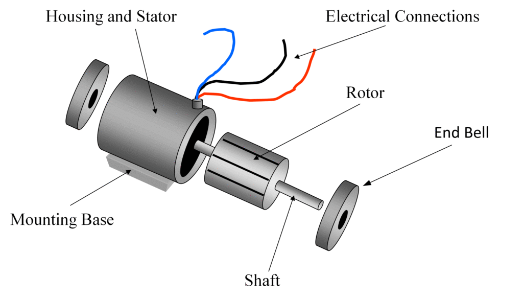
When it comes to understanding how to wire an induction motor, an induction motor wiring diagram is an essential tool. This diagram provides a visual representation of the electrical connections and components involved in powering and controlling an induction motor. By following a wiring diagram, you can ensure that the motor is connected correctly and functions as intended.
Importance of Induction Motor Wiring Diagrams
Induction motor wiring diagrams are essential for several reasons:
- They help ensure that the motor is connected correctly to the power source, control devices, and other components.
- They provide a reference for troubleshooting electrical issues or making modifications to the motor’s wiring.
- They are crucial for maintaining safety by following proper wiring practices and avoiding electrical hazards.
Reading and Interpreting Induction Motor Wiring Diagrams
When reading an induction motor wiring diagram, it’s important to understand the symbols and labels used to represent different components and connections. Here are some key points to keep in mind:
- Identify the main power source and how it connects to the motor.
- Understand the function of each wire and where it should be connected.
- Pay attention to any control devices, switches, or other components that are part of the motor’s circuit.
Using Induction Motor Wiring Diagrams for Troubleshooting
Induction motor wiring diagrams are invaluable for troubleshooting electrical problems. By referencing the diagram, you can easily identify potential issues such as loose connections, faulty components, or incorrect wiring. Here are some tips for using wiring diagrams for troubleshooting:
- Follow the wiring diagram step by step to trace the electrical path and identify any discrepancies.
- Check for continuity and proper voltage at key points in the circuit to pinpoint the source of the problem.
- Refer to the manufacturer’s documentation for specific troubleshooting procedures related to the motor model.
Safety Tips for Working with Induction Motor Wiring Diagrams
Working with electrical systems and wiring diagrams can be hazardous if proper precautions are not taken. Here are some safety tips to keep in mind:
- Always disconnect the power source before working on the motor or its wiring.
- Use insulated tools and equipment to prevent electrical shocks or short circuits.
- Double-check all connections and wiring before applying power to the motor.
- If you are unsure about any aspect of the wiring diagram or motor connections, consult a qualified electrician or technician.
Induction Motor Wiring Diagram
WIRING DIAGRAM STAR-DELTA CONNECTION IN 3-PHASE INDUCTION MOTOR

Clarke Single Phase Induction Motor Wiring Diagram

Types of Single Phase Induction Motors | Single Phase Induction Motor

Types of Single Phase Induction Motors | Single Phase Induction Motor

wiring – How to wire up single phase induction motor? – Electrical

Types of Single Phase Induction Motors | Single Phase Induction Motor
