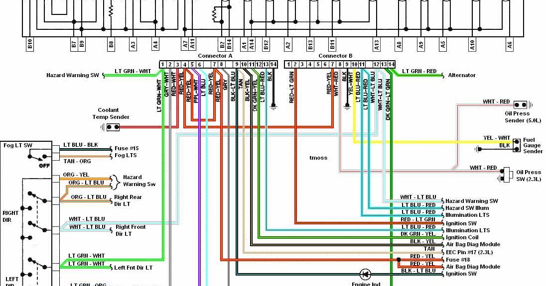
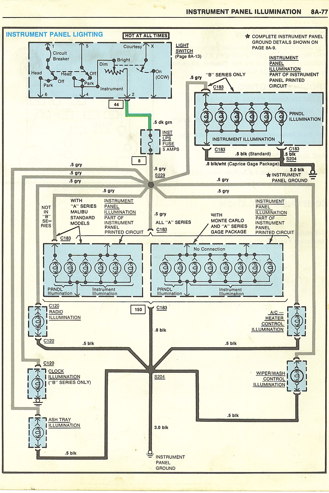
Instrument Cluster Wiring Diagrams are crucial tools for understanding the electrical system of a vehicle. They provide a detailed layout of the wiring connections for the various components within the instrument cluster, such as the speedometer, tachometer, fuel gauge, and warning lights. By studying these diagrams, mechanics can identify wiring issues, trace electrical faults, and make necessary repairs to ensure the proper functioning of the instrument cluster.
Why are Instrument Cluster Wiring Diagrams essential?
Instrument Cluster Wiring Diagrams are essential for the following reasons:
- Helps in understanding the electrical connections within the instrument cluster
- Aids in troubleshooting electrical problems effectively
- Guides in performing repairs and replacements of faulty wiring components
- Ensures the proper functioning of the instrument cluster and its various components
How to read and interpret Instrument Cluster Wiring Diagrams effectively
Reading and interpreting Instrument Cluster Wiring Diagrams may seem daunting at first, but with practice and understanding, it becomes easier. Here are some tips to help you read and interpret these diagrams effectively:
- Start by familiarizing yourself with the symbols and color-coding used in the diagram
- Identify the components within the instrument cluster and their corresponding wiring connections
- Follow the wiring paths to trace electrical connections and locate potential faults
- Refer to the key or legend provided in the diagram to understand the symbols and abbreviations used
Using Instrument Cluster Wiring Diagrams for troubleshooting electrical problems
Instrument Cluster Wiring Diagrams are invaluable tools for troubleshooting electrical problems in vehicles. By following the wiring paths and identifying potential faults, mechanics can quickly diagnose and address issues within the instrument cluster. Here are some steps to effectively use wiring diagrams for troubleshooting:
- Inspect the wiring connections within the instrument cluster for any signs of damage or wear
- Use a multimeter to test the continuity and voltage of the wiring connections
- Refer to the wiring diagram to locate the source of the electrical problem and make necessary repairs
- Verify the repairs by testing the instrument cluster to ensure proper functioning
When working with electrical systems and using Instrument Cluster Wiring Diagrams, it is essential to prioritize safety. Here are some safety tips and best practices to keep in mind:
- Always disconnect the battery before working on any electrical components
- Use insulated tools to prevent electrical shock
- Avoid working on electrical systems in wet or damp conditions
- Refer to the vehicle’s service manual for specific safety precautions and guidelines
Instrument Cluster Wiring Diagram
Instrument Cluster Wiring Diagrams Of 1987 Ford Mustang 3rd Generation

Instrument Cluster Wiring Diagram

Gm Instrument Cluster Wiring Diagram

Bmw E36 Instrument Cluster Wiring Diagram

1986 C10 Instrument Cluster Wiring Diagram

2005 Chevy Silverado Instrument Cluster Wiring Diagram
