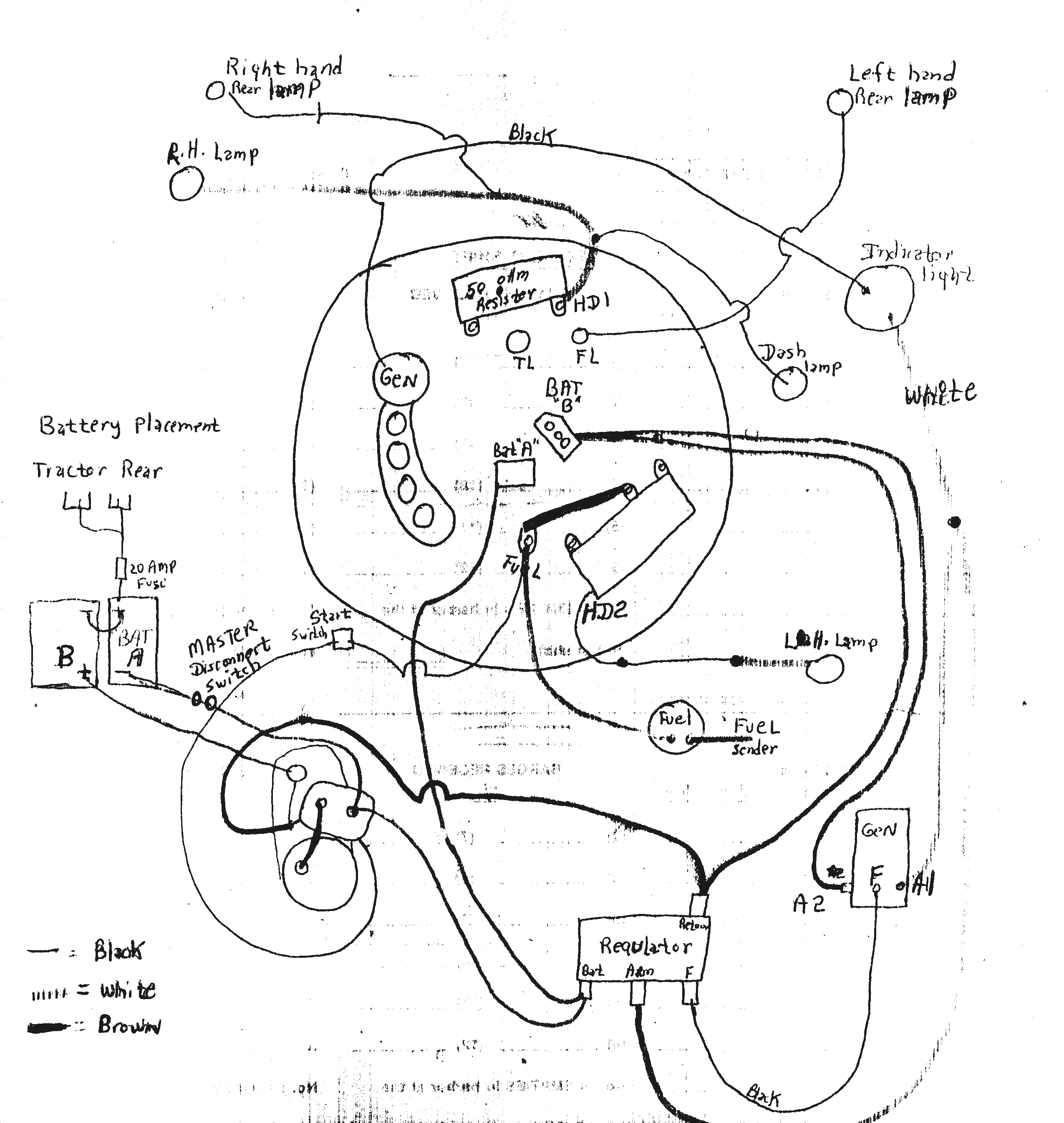
When it comes to maintaining and troubleshooting the electrical system of a John Deere 4020 tractor, having a reliable wiring diagram is essential. A John Deere 4020 Wiring Diagram provides a visual representation of the electrical connections and components within the tractor, making it easier to identify and resolve any electrical issues that may arise.
Why John Deere 4020 Wiring Diagrams are Essential
- Helps in understanding the layout of the electrical system
- Aids in identifying connections and components
- Assists in troubleshooting electrical problems
- Ensures proper maintenance and repairs
Reading and Interpreting John Deere 4020 Wiring Diagrams
When reading a John Deere 4020 Wiring Diagram, it is important to understand the symbols and color codes used to represent different components and connections. By familiarizing yourself with the key elements of the diagram, you will be able to navigate through the electrical system more effectively.
Using Wiring Diagrams for Troubleshooting Electrical Problems
John Deere 4020 Wiring Diagrams are invaluable tools when it comes to troubleshooting electrical issues in the tractor. By following the wiring diagram and tracing the electrical paths, you can pinpoint the source of the problem and take the necessary steps to fix it. Whether it’s a faulty connection, a damaged component, or a short circuit, the wiring diagram will guide you through the troubleshooting process.
Importance of Safety
Working with electrical systems can be dangerous, so it is important to prioritize safety when using wiring diagrams. Here are some safety tips and best practices to keep in mind:
- Always disconnect the battery before working on the electrical system
- Use insulated tools to avoid electrical shocks
- Avoid working in wet or damp conditions
- Double-check all connections and wiring before turning the tractor back on
John Deere 4020 Wiring Diagram
John Deere 4020 Wiring Diagram

Jd 4020 Wiring Diagram

john deere 4020 24 volt wiring diagram – ShaznieSanaa

John Deere 4020 Wiring Schematic

John Deere 4020 12v Wiring Diagram – Wiring Diagram and Schematic

John Deere 4020 24v To 12v Conversion Wiring Diagram | wiring idas
