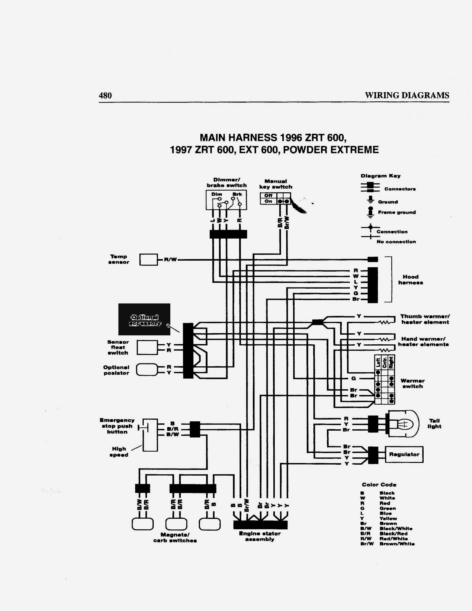
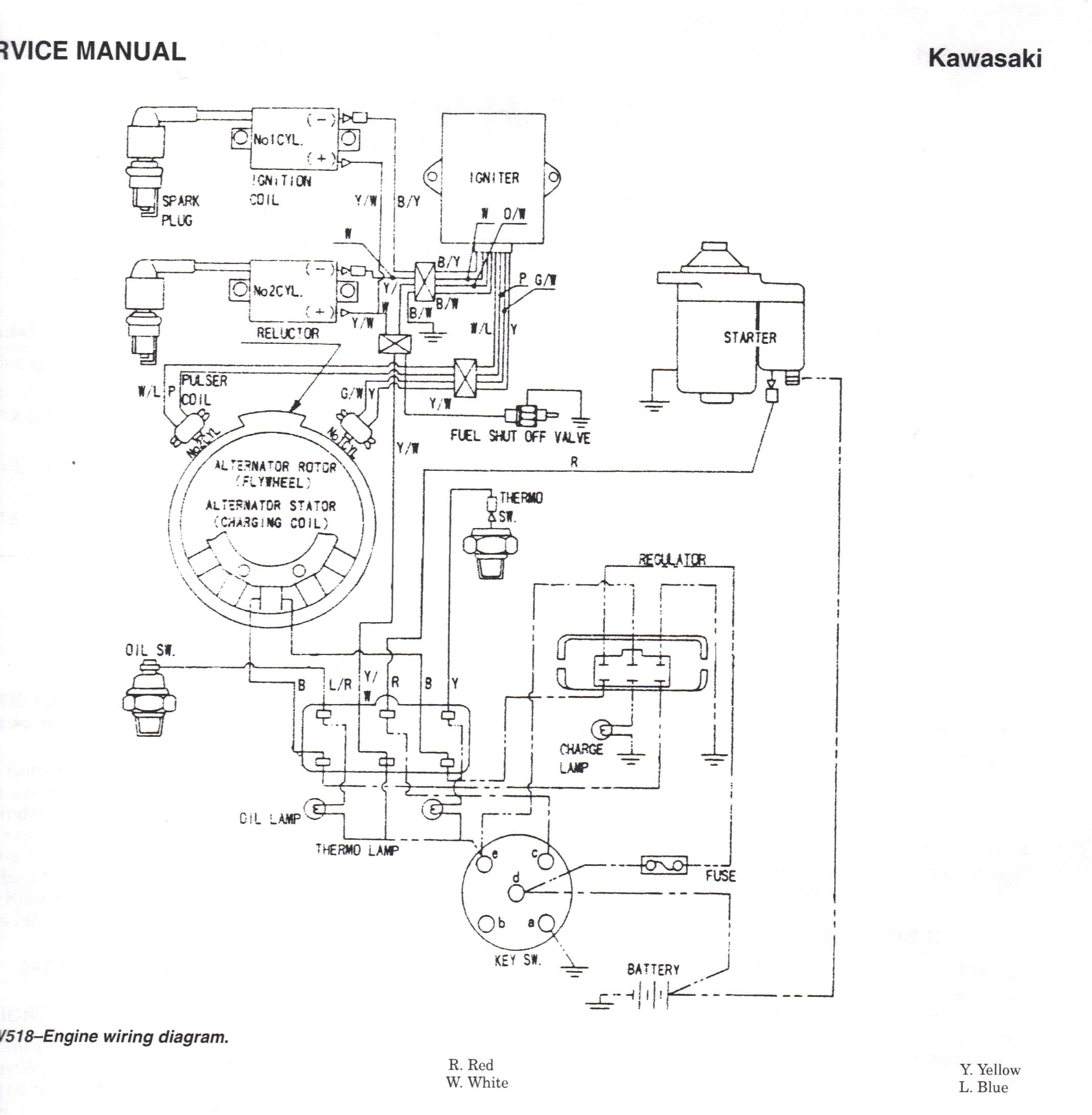
John Deere La105 Wiring Diagram is a crucial tool for anyone working on the electrical systems of a John Deere La105 tractor. This diagram provides a visual representation of the electrical connections and components within the tractor’s wiring system, helping users to understand how everything is connected and functioning.
Why John Deere La105 Wiring Diagram are essential
Understanding and utilizing John Deere La105 Wiring Diagram is essential for several reasons:
- Ensures proper installation of new electrical components
- Aids in diagnosing electrical issues
- Helps in troubleshooting and repairing electrical problems
- Ensures safety by preventing incorrect connections
How to read and interpret John Deere La105 Wiring Diagram effectively
Reading and interpreting a John Deere La105 Wiring Diagram may seem daunting at first, but with the right approach, it can be a valuable tool:
- Start by identifying the key components listed in the diagram
- Follow the flow of the wiring from one component to another
- Understand the symbols and color codes used in the diagram
- Refer to the legend or key for any specific information
Using John Deere La105 Wiring Diagram for troubleshooting electrical problems
When faced with electrical issues in a John Deere La105 tractor, the wiring diagram can be a lifesaver:
- Identify the affected circuit or component in the diagram
- Trace the wiring to locate any potential faults or breaks
- Check for continuity using a multimeter to pinpoint the issue
- Refer to the diagram to find the correct wiring connections
Importance of safety when working with electrical systems
Working with electrical systems, including using wiring diagrams, requires utmost caution to avoid accidents or damage:
- Always disconnect the battery before working on the electrical system
- Use insulated tools to prevent electrical shocks
- Avoid working on electrical systems in wet or damp conditions
- Refer to the tractor’s manual for specific safety guidelines
John Deere La105 Wiring Diagram
John Deere La105 Wiring Diagram

John Deere La105 Wiring Schematic – Wiring Diagram

John Deere La105 Wiring Schematic – Wiring Diagram

John Deere La105 Wiring Diagram

John Deere La105 Wiring Diagram

John Deere La105 Wiring Schematic – Wiring Diagram
