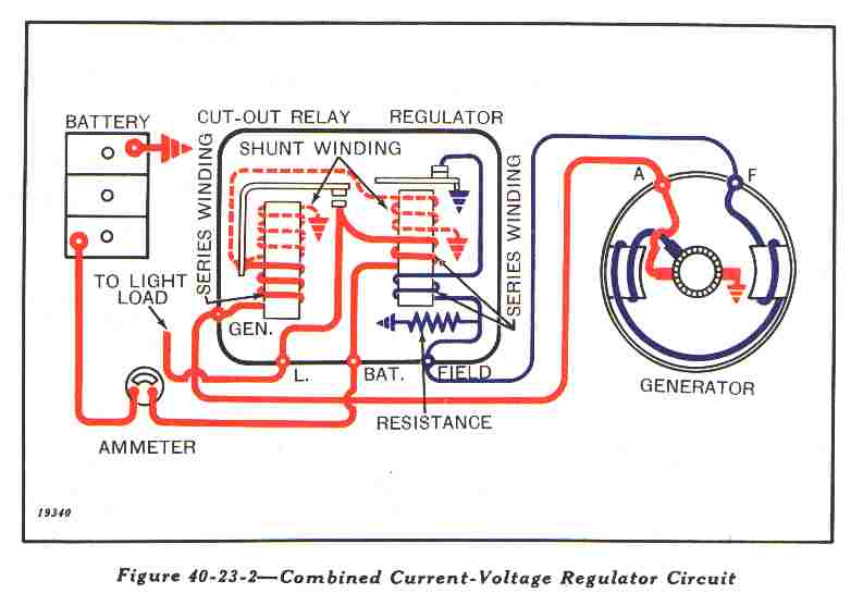
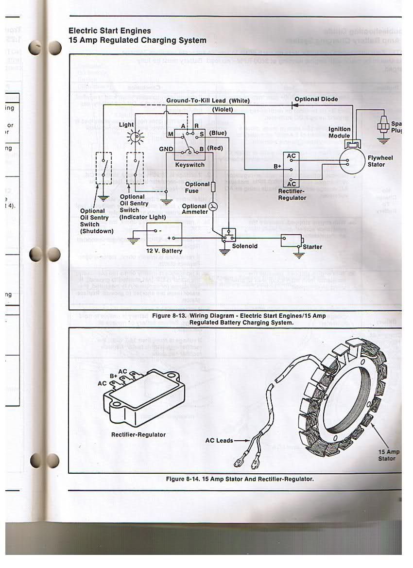
John Deere Voltage Regulator Wiring Diagrams are essential for understanding the electrical system of your John Deere equipment. These diagrams provide a detailed illustration of the wiring connections, components, and their functions within the voltage regulator system. By referring to these diagrams, you can effectively troubleshoot and repair any electrical issues that may arise.
Importance of John Deere Voltage Regulator Wiring Diagrams
- Helps in understanding the electrical layout of the equipment
- Provides a visual representation of the wiring connections
- Aids in diagnosing and fixing electrical problems
Reading and Interpreting John Deere Voltage Regulator Wiring Diagrams
When looking at a John Deere Voltage Regulator Wiring Diagram, it’s important to understand the symbols and color codes used. Each component is represented by a specific symbol, and the color-coding helps identify the wiring connections. By following the wiring paths and connections, you can trace the flow of electricity and pinpoint any issues that may be causing a malfunction.
Using Wiring Diagrams for Troubleshooting
- Identify the specific component or circuit that is malfunctioning
- Trace the wiring connections to locate any breaks, shorts, or loose connections
- Use a multimeter to test the continuity and voltage at different points in the circuit
- Compare the actual wiring with the diagram to ensure it matches correctly
Safety Tips for Working with Electrical Systems
- Always disconnect the power source before working on any electrical components
- Use insulated tools to avoid electrical shocks
- Avoid working on electrical systems in wet or damp conditions
- Wear protective gear such as gloves and safety goggles
- Double-check your work before turning the power back on
John Deere Voltage Regulator Wiring Diagram
Electrical Info

Yesterday Tractor Wiring Diagram For Voltage Regulator

Q&A: Troubleshooting John Deere 4020 Gas Tractor Voltage Regulator

Wiring Diagram John Deere 110 Lawn Tractor – Wiring Diagram and Schematics

Wiring Diagram For John Deere 757

John Deere Lx176 Wiring Diagram
