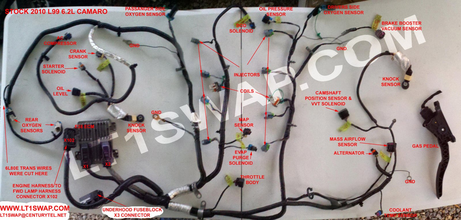
Ls Engine Wiring Diagram
An Ls Engine Wiring Diagram is a detailed schematic that illustrates the electrical connections and components of an LS engine. This diagram is essential for understanding how the various electrical systems work together to power and control the engine.
Why are Ls Engine Wiring Diagrams essential?
- Helps in understanding the electrical system of the engine
- Aids in diagnosing and troubleshooting electrical issues
- Guides in performing modifications or upgrades to the electrical system
How to read and interpret Ls Engine Wiring Diagrams effectively
When reading an LS Engine Wiring Diagram, it’s important to follow the color-coding of wires and symbols to identify different components. The key is to understand the flow of electricity and how each part of the system interacts with one another.
Using Ls Engine Wiring Diagrams for troubleshooting electrical problems
- Identify the specific circuit or component causing the issue
- Trace the wiring to locate any breaks, shorts, or loose connections
- Use a multimeter to test for continuity and voltage at various points
Importance of safety when working with electrical systems
When working with electrical systems and using wiring diagrams, safety should always be a top priority. Here are some safety tips and best practices:
- Always disconnect the battery before working on any electrical components
- Use insulated tools to prevent electric shock
- Avoid working on electrical systems in wet or damp conditions
- If you’re unsure about a certain procedure, consult a professional mechanic
Ls Engine Wiring Diagram
Ls Engine Wiring Schematic

2001 Ls1 Engine Wiring Diagram

Wiring Diagrams For Chevy Ls Engines

Wiring information for 1998 to 2002 Camaro & Firebird LS1

Gm Ls3 Crate Engine Wiring Diagram – General Wiring Diagram

Ls Swap Wiring Pinout
