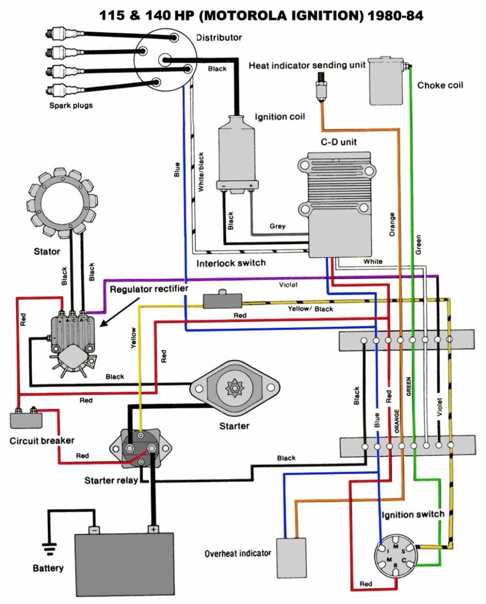
When it comes to maintaining and troubleshooting your boat’s electrical system, having a clear understanding of the Mercruiser Trim Solenoid Wiring Diagram is essential. This diagram provides a detailed outline of the wiring connections for the trim solenoid, allowing you to easily identify and resolve any electrical issues that may arise.
Why Mercruiser Trim Solenoid Wiring Diagrams are Essential
Understanding the Mercruiser Trim Solenoid Wiring Diagram is crucial for several reasons:
- Ensures proper installation of the trim solenoid
- Helps in diagnosing electrical problems quickly
- Facilitates easy repairs and maintenance of the trim system
Reading and Interpreting Mercruiser Trim Solenoid Wiring Diagram
When reading a Mercruiser Trim Solenoid Wiring Diagram, it’s important to pay attention to the following key components:
- Wire colors and labels
- Connection points and terminals
- Fuse locations and ratings
Using Mercruiser Trim Solenoid Wiring Diagram for Troubleshooting
When troubleshooting electrical problems on your boat, the Mercruiser Trim Solenoid Wiring Diagram can be a valuable tool. By following the wiring diagram and checking for continuity, shorts, or open circuits, you can quickly identify and resolve any issues that may be affecting the trim system.
Importance of Safety
Working with electrical systems can be hazardous, so it’s important to prioritize safety at all times. Here are some key safety tips to keep in mind:
- Always disconnect the battery before working on any electrical components
- Use insulated tools to prevent electric shock
- Avoid working on electrical systems in wet or damp conditions
- Refer to the manufacturer’s guidelines and warnings when using wiring diagrams
Mercruiser Trim Solenoid Wiring Diagram
Wiring Diagram For 3 Button Single Solenoid Trim Pump For Mercruiser

Mercruiser Power Trim Solenoid Wiring Diagram – Wiring Diagram
Mercruiser Trim Solenoid Wiring Diagram For Your Needs
Mercury Outboard Power Trim Wiring Diagram – Wiring Draw

Wiring Diagram For 3 Button Single Solenoid Trim Pump For Mercruiser

Mercruiser Trim Solenoid Wiring Diagram – Free Wiring Diagram
