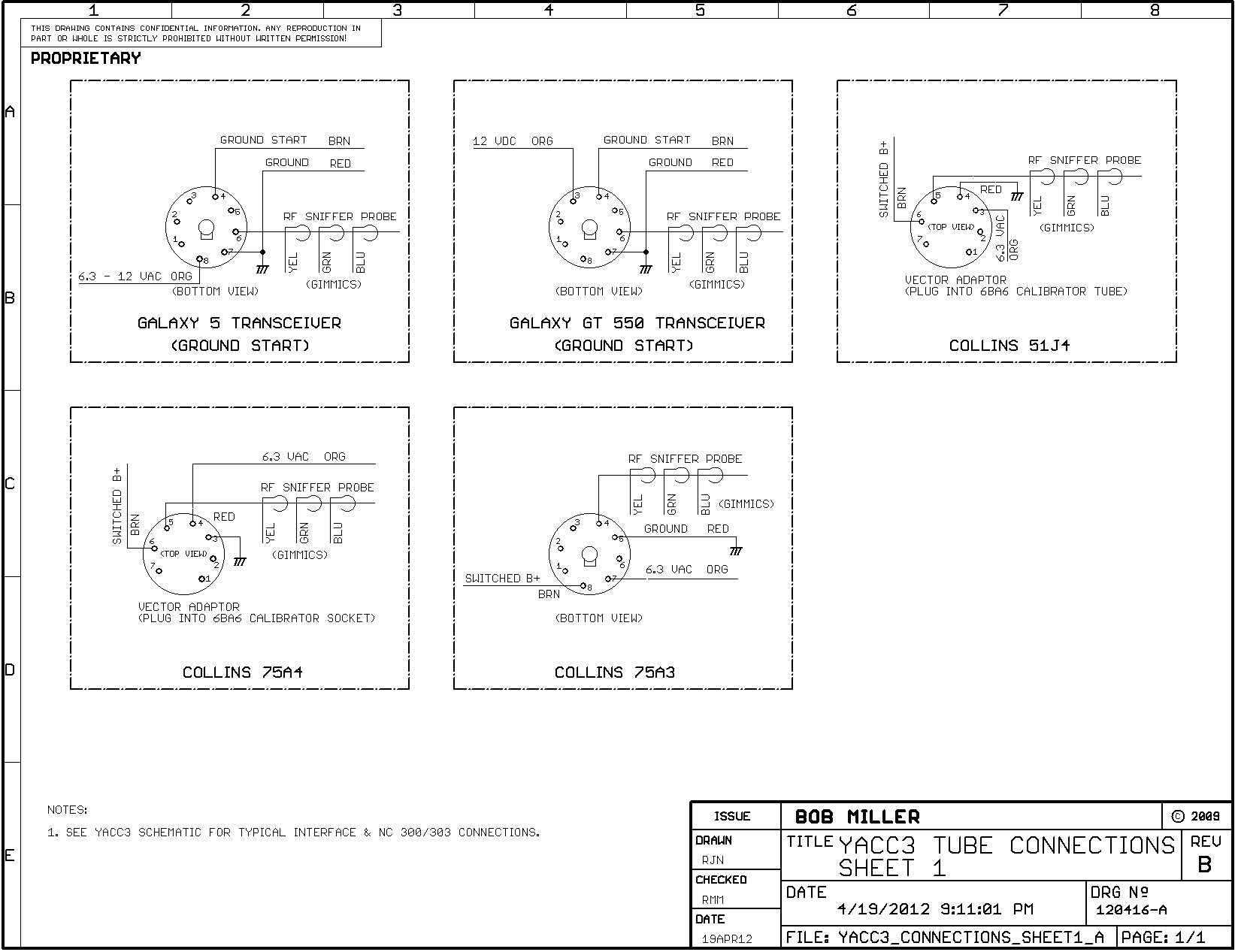
When it comes to understanding the intricacies of electrical systems in welding equipment, the Miller 14 Pin Connector Wiring Diagram is an invaluable tool. This diagram provides a detailed map of the connections between various components in the welding machine, ensuring that everything is properly wired and functioning correctly. By following this diagram, technicians can troubleshoot issues, make repairs, and maintain the equipment with ease.
Importance of Miller 14 Pin Connector Wiring Diagram
- Ensures proper connection of components
- Aids in troubleshooting electrical issues
- Facilitates maintenance and repairs
Reading and Interpreting Miller 14 Pin Connector Wiring Diagram
Reading a Miller 14 Pin Connector Wiring Diagram may seem daunting at first, but with a little practice, it can become second nature. The key is to understand the symbols and color codes used in the diagram, as well as the layout of the connections. By familiarizing yourself with these elements, you can quickly identify the components and their respective connections.
Using Miller 14 Pin Connector Wiring Diagram for Troubleshooting
- Identify potential problem areas
- Check for loose connections or damaged wires
- Trace the flow of electricity to pinpoint issues
Safety Tips for Working with Miller 14 Pin Connector Wiring Diagram
- Always disconnect power before working on the equipment
- Use insulated tools to avoid electric shocks
- Avoid working on wet surfaces or in damp conditions
- Double-check all connections before powering up the equipment
Miller 14 Pin Connector Wiring Diagram
Miller 14 Pin Connector Wiring Diagram – Wiring Diagram
Miller 14 Pin Connector Wiring Diagram – Free Wiring Diagram

miller 14 pin connector wiring diagram – TansyMaryam

Miller 14 Pin Connector Wiring Diagram Database

miller 14 pin connector wiring diagram – DerecAniruddha
