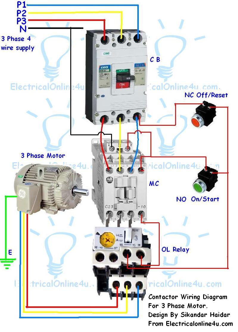
When it comes to understanding and fixing electrical issues in machinery or equipment, having a thorough understanding of the Start Stop Button Wiring Diagram is crucial. This diagram provides a visual representation of the electrical connections and components involved in the start and stop functions of a machine.
Importance of Start Stop Button Wiring Diagram
- Helps identify the correct wiring connections for the start and stop buttons
- Aids in troubleshooting electrical issues related to the start and stop functions
- Ensures proper installation and operation of the start and stop buttons
Reading and Interpreting Start Stop Button Wiring Diagram
Start Stop Button Wiring Diagrams can seem overwhelming at first glance, but with some guidance, they can be easy to understand and interpret. Here’s how:
- Identify the start and stop buttons on the diagram
- Follow the lines to see how the buttons are connected to other components
- Pay attention to symbols and labels for different electrical components
Using Start Stop Button Wiring Diagram for Troubleshooting
When facing electrical problems with the start and stop functions of a machine, the Start Stop Button Wiring Diagram can be a valuable tool for troubleshooting. Here’s how:
- Check for loose or disconnected wires indicated on the diagram
- Verify if the start and stop buttons are properly connected to the control system
- Look for any damaged components or faulty connections
It’s crucial to always prioritize safety when working with electrical systems and using wiring diagrams. Here are some safety tips and best practices to keep in mind:
- Always turn off the power supply before working on electrical components
- Use insulated tools to prevent electric shock
- Double-check all connections before energizing the system
- Seek assistance from a qualified electrician if unsure about any aspect of the wiring diagram
Start Stop Button Wiring Diagram
Start Stop Circuit – What They Are, Where They Are Used And How To Wire

How to make Start and Emergency Stop Switch Wiring Diagram | emergency

Wiring Diagram For 3 Phase Motor Starter With Stop Start Buttons

Multiple Push Button Stations. Three Wire Control Multiple Stations

Start Stop Push Button Wiring Diagram

Wiring Diagram For A Starter Controlling A 480v Motor With 120v Start
