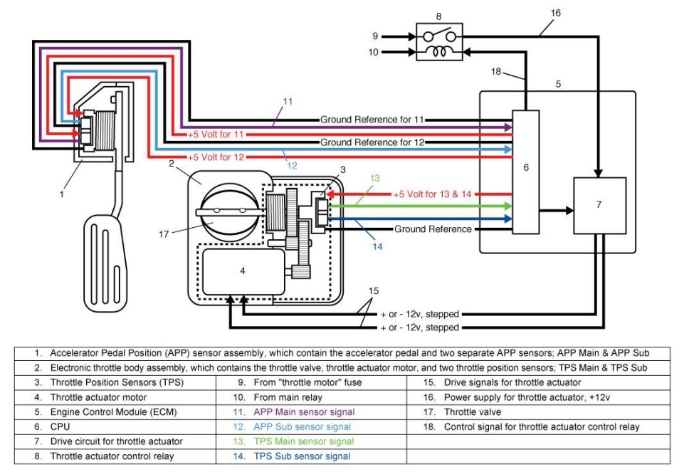
When it comes to understanding the intricacies of your vehicle’s electrical system, having a clear Tps Sensor Wiring Diagram is essential. This diagram provides a detailed visual representation of the wiring connections for the Throttle Position Sensor (TPS) in your vehicle, allowing you to troubleshoot and diagnose any potential issues effectively. By referring to the Tps Sensor Wiring Diagram, you can easily identify the various components and their connections, making it easier to maintain and repair your vehicle.
Why Tps Sensor Wiring Diagram are essential
Understanding the Tps Sensor Wiring Diagram is crucial for several reasons:
- Helps identify the correct wiring connections for the TPS sensor
- Aids in troubleshooting electrical issues related to the TPS sensor
- Ensures proper maintenance and repair of the TPS sensor
How to read and interpret Tps Sensor Wiring Diagram effectively
Reading and interpreting Tps Sensor Wiring Diagram may seem daunting at first, but with a few key tips, you can navigate through the diagram with ease:
- Start by identifying the key components of the TPS sensor, such as the power source, ground connection, and signal wire.
- Refer to the color codes and labels on the diagram to match the wiring connections accurately.
- Follow the wiring paths to ensure that the connections are correctly established and avoid any potential shorts or open circuits.
How Tps Sensor Wiring Diagram are used for troubleshooting electrical problems
When faced with electrical issues related to the TPS sensor, the Tps Sensor Wiring Diagram can be your best ally in troubleshooting the problem:
- Identify any loose or damaged wiring connections that may be causing the issue.
- Check for continuity and voltage levels using a multimeter to pinpoint the source of the problem accurately.
- Compare the actual wiring connections to the diagram to ensure they match and make any necessary adjustments if needed.
Importance of safety when working with electrical systems
Working with electrical systems, including Tps Sensor Wiring Diagram, requires utmost caution and adherence to safety protocols:
- Always disconnect the battery before working on any electrical components to prevent any accidental shorts or shocks.
- Use insulated tools and gloves to protect yourself from electrical hazards.
- Double-check all connections and wiring before reassembling the components to avoid any potential issues.
Tps Sensor Wiring Diagram
P0122 Code: Throttle Position Sensor/Switch A Circuit Low Input – In

3, 4, 5, 6, & 8 Wire Throttle Position Sensor Wiring Diagram – TPS

Ford Tps Wiring Diagram

2008 F250 5.4 Throttle Position Sensor Wiring Diagram

Accelerator Pedal Position Sensor Wiring Diagram – inspirenetic
