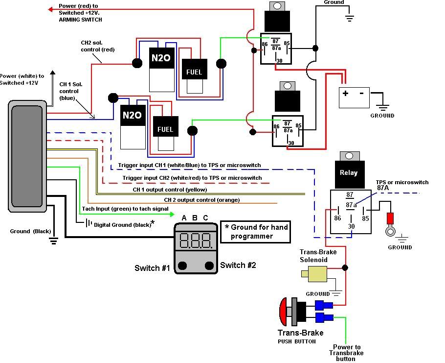
Transbrake Nitrous Wiring Diagrams are crucial tools for mechanics and enthusiasts looking to understand the electrical systems in vehicles equipped with transbrake and nitrous systems. These diagrams provide a visual representation of how the components are connected and powered, helping users troubleshoot issues, plan installations, and ensure proper functioning of the systems.
Why Transbrake Nitrous Wiring Diagrams are Essential
- Help in understanding the electrical layout of transbrake and nitrous systems
- Aid in troubleshooting electrical issues
- Ensure proper installation and functioning of the systems
Reading and Interpreting Transbrake Nitrous Wiring Diagrams
When looking at a Transbrake Nitrous Wiring Diagram, it’s important to understand the symbols and layout used. Here are some key points to keep in mind:
- Identify the components and their connections
- Follow the flow of current through the system
- Pay attention to color codes and wire sizes
Using Transbrake Nitrous Wiring Diagrams for Troubleshooting
Transbrake Nitrous Wiring Diagrams can be invaluable when diagnosing electrical problems in vehicles. By following the diagram and testing the connections, users can pinpoint issues such as faulty wiring, blown fuses, or malfunctioning components.
Importance of Safety
When working with electrical systems and using wiring diagrams, it’s essential to prioritize safety. Here are some tips to keep in mind:
- Always disconnect the battery before working on the electrical system
- Use appropriate tools and equipment to avoid electrical shocks
- Double-check all connections and wiring before powering up the system
Transbrake Nitrous Wiring Diagram
Wiring Diagram For Nitrous Solenoids

Transbrake Nitrous Wiring Diagram – Wiring Diagram

nitrous wiring diagram with transbrake – MyiaKathleen
nitrous wiring diagram with transbrake – MyiaKathleen

nitrous wiring diagram with transbrake

Nitrous with transbrake schematic, overview – LS1TECH – Camaro and
