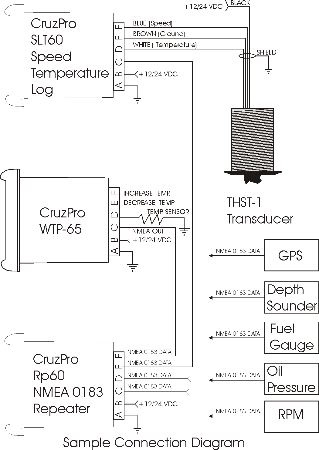
When it comes to understanding the electrical components of your vehicle, having a Vdo Rev Counter Wiring Diagram can be extremely helpful. This diagram provides a detailed illustration of the wiring connections for your rev counter, allowing you to troubleshoot any electrical issues that may arise.
Why Vdo Rev Counter Wiring Diagrams are Essential
Vdo Rev Counter Wiring Diagrams are essential for several reasons:
- They provide a visual representation of the wiring connections, making it easier to identify and fix any issues.
- They help ensure that the rev counter is properly connected to the electrical system, preventing potential damage or malfunctions.
- They serve as a reference guide for future maintenance or upgrades to the rev counter.
Reading and Interpreting Vdo Rev Counter Wiring Diagrams
When reading a Vdo Rev Counter Wiring Diagram, it’s important to:
- Identify the different components and their corresponding symbols.
- Follow the wiring connections from the rev counter to the electrical system.
- Pay attention to the color codes and labels used in the diagram.
Using Vdo Rev Counter Wiring Diagrams for Troubleshooting
Vdo Rev Counter Wiring Diagrams can be used for troubleshooting electrical problems by:
- Checking for loose or damaged connections.
- Testing the voltage and continuity of the wiring using a multimeter.
- Comparing the actual wiring connections to the diagram to identify any discrepancies.
Importance of Safety
Working with electrical systems can be dangerous, so it’s important to follow these safety tips:
- Always disconnect the battery before working on any electrical components.
- Avoid working on the wiring with wet hands or in wet conditions.
- Use insulated tools to prevent electrical shock.
- If you’re unsure about any aspect of the wiring diagram, consult a professional mechanic.
Vdo Rev Counter Wiring Diagram
Vdo Rev Counter Wiring Diagram

Vdo Rev Counter Wiring Diagram

Vdo Rev Counter Wiring Diagram

Vdo rev counter | The Late Bay

Vdo Senders Wiring Diagrams

Electrics – VDO Rev Counter Wiring | Volkszone Forum
