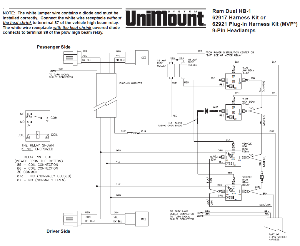
When dealing with the intricate wiring of a Western Unimount Plow Solenoid, having a clear and detailed diagram is crucial. A Western Unimount Plow Solenoid Wiring Diagram provides a visual representation of the electrical connections and functions of the plow system, making it easier to understand and troubleshoot any issues that may arise.
Why Western Unimount Plow Solenoid Wiring Diagrams are Essential
- Help to identify the correct wiring connections
- Ensure proper installation and functioning of the plow system
- Assist in troubleshooting electrical problems
- Prevent short circuits and other electrical issues
How to Read and Interpret Western Unimount Plow Solenoid Wiring Diagram
When looking at a Western Unimount Plow Solenoid Wiring Diagram, it’s important to pay attention to the symbols and color codes used. Each component and connection will be clearly labeled, allowing you to follow the flow of electricity through the system. Understanding the diagram will help you make accurate installations and repairs.
Using Western Unimount Plow Solenoid Wiring Diagram for Troubleshooting
When faced with electrical problems in your plow system, referring to the wiring diagram can help you pinpoint the source of the issue. By tracing the electrical connections and identifying any faults or breaks in the wiring, you can efficiently troubleshoot and repair the problem. The diagram acts as a roadmap for diagnosing and fixing electrical faults.
Importance of Safety
Working with electrical systems, including wiring diagrams for plow solenoids, requires caution and adherence to safety guidelines. To ensure your safety and prevent electrical hazards, consider the following tips:
- Always disconnect the power source before working on the wiring
- Use insulated tools to avoid electrical shocks
- Avoid working on wet or damp surfaces to prevent electrical accidents
- Double-check your connections and follow the wiring diagram accurately
- If you’re unsure of any step, seek professional help to avoid risking injury or damage
Western Unimount Plow Solenoid Wiring Diagram
western plow solenoid wiring diagram – JeannieElli

western plow solenoid wiring diagram – JeannieElli

Unimount Western Plow Wiring Diagram

Western Unimount Plow Lights Wiring Diagram

9 pin western unimount plow wiring diagram

Western Unimount Wiring Diagram – Cadician's Blog
